Introduction
Woodworking and Electronics/Computer gadgets are my two life-long hobbies. Recently, I noticed that computer numerical control (CNC) machines for woodworking become quite popular and the low-end CNC machines become affordable for hobby uses. To explore the possibility, I bought a CNC-3018 by SainSmart from Ebay. It belongs to the mini CNC category but on the larger end. The operation surface is about 280mm by 170mm.
Once I received the machine, I tried to figure out about how to use it. Because my wife started learning Chinese Calligraphy two years ago, I thought it might be an interesting application to carve Chinese calligraphy on wood.
Since I could not find any reference, I have to learn how to do it myself. After three months, I have generated a few of such carvings as shown in the figure at the end of this blog. I showed these pieces of my work to a few friends and the people in my wife’s calligraphy study group. Quite a few people are interested in how I did that. Some of them are also want to learn how to do that themselves. I thought that it could be helpful to others if I can put what I learned together for other people, so they can learn from my success and the mistakes that I made during the process. This blog is a step-by-step guide produce wood carvings of Chinese calligraphy using a CNC machine.
Overall process
The process of generating Chinese calligraphy wood caving involves the following steps:
- Digitize the calligraphy to raster (bit-map) form and generate outlines of the calligraphy characters;
- Generate the computer code, called g-code, of the outlines to be used by the CNC;
- For wood carving with the characters above the wood surface, traditionally called “阳文”, generate the g-code for the CNC to remove the part of the wood surface where are no strikes of the calligraphic characters;
- Carve the character outlines onto wood surface using the g-code generated in step 2;
- Remove the parts of the wood surface with no characters strikes using the g-code generated from step 3;
- Manually clean-up and refine.
These steps are described in the paragraphs below in detail. The whole process will become clearer.
Step I: Generating bit-map (raster) graphic presentation of calligraphy and pre-processing
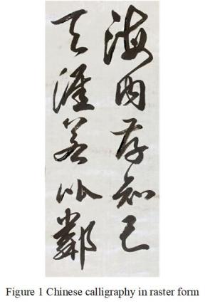
Chinese calligraphy characters are commonly written on paper by using brushes. They can be converted into digital form by taking a photo using a digital camera or by using a scanner. It is desirable for characters to have clear outlines. However, usually, due to brush marks, their outlines are not always clean. Thus, some pre-processing must be done to clean up. Moreover, if some brush strikes are too thin, it would be difficult to carve them on wood. Thus, the thin strikes should be made thicker or deleted, as appropriate. Figure 1 below shows such raster form of a calligraphy.
Such generated digital representation of the calligraphy is usually in raster, or bit-map, form. For further processing, the outlines of the strikes of calligraphic words are extracted. The open-source software Inkscape can be used to extract such outlines from the calligraphy in bit-map format. Inkscape can be downloaded online for free.
The procedure of generating the outlines from bit-mapped graphics can be found here.
The drawing of the generated calligraphic character outlines in Inkscape is saved in a DXF (Autocad Drawing eXchange Format) file with extension of .dxf. The generated .dxf file can be opened with a number drawing programs for further processing. I use Microsoft Visio for this purpose.
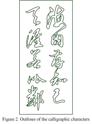
After it is opened by Visio, it should first be ungrouped. Then, the drawing is scaled to the desired size and is further cleaned up. Once all of the strikes/characters have clean outlines, in order to define the wood cutting area and for alignment purpose, a rectangular box with line width of ¼ pt is added. The outline drawing generated from the calligraphy in Figure 1 is shown in Figure 2.
The drawing is then saved in the DXF format. The resulting .dxf file is used to generate a g-code file, which can be used by the CNC machine to cut the outlines onto the wood board to be used.
The Visio drawing is also saved for create the contours around the calligraphic characters as to be discussed below.
Step II: Generating g-code of the character outlines
The open-source program dfx2gcode is used to convert the .dxf file containing the outlines to g-code. The conversion process is quite straightforward. However, there are a few things need to pay attention.
First, the program in its current form, assumes that the measurement unit in the .dxf file is in inch. Thus, during editing, the measurement unit must also set to be inch, even though the other parameters are defined in millimeters.
Second, it is necessary to set the cutting depth per pass and number of passes and feed rates in Option/Configuration/Machine config submenu. Since it would be desirable for the outlines cut on the wood as thin as possible, a 20 degree/0.1 mm V Shape CNC bit is used. As the tip of the bits is quite thin, it is easy to break. Thus, the cutting parameters need to be set conservatively. When the cutting depth is set to be 1.2mm, two or three passes, each of which is 0.6 or 0.4 mm are used. Moreover, the feed speed is set to between 100 to 200 mm/minute.
To start converting, in the file menu, click the item open and open the .dxf file to be converted. Then in the export menu, do “optimize paths” and “export shapes.” A file with extension .ngc containing the g-code will be generated after a short time. The generated .ngc file is going to be used for cutting the calligraphic character outlines as to be discussed later.
Step III Generation of Visio drawing for surface cleaning
For wood carving with the calligraphic characters on top of the wood surface, traditionally called “阳文”, it is necessary remove the part of the wood surfaces, with a depth of about 1 mm (1.2mm in my carvings), where there are no character strikes. To do so, the first step is to define the contour around these character strikes.
To reduce the CNC carving time, it is desirable to use bits what can take out as much wood surfaces as possible at a time, i.e., using a bit with a larger size. On the other hand, the bits cannot be too large in order to follow the character contour as close as possible. To satisfy both considerations, CNC bits with 2mm to 3mm diameter with a “fish tail” tip, which can generate flat wood surface after cutting, can be used.
In this operation, the key step is to generate a contour around the characters. The CNC bit will first cut the wood along the contour. The contour should be close to the character outlines but the bit will at most touch the outlines but not cut the wood inside the outlines. In other words, the distance between the line of the contour and the closest outline should be at close to, but larger than the radius of the CNC bit.
To generate such a contour, we change the line width of the outlines of the Visio file created previously to be slightly larger than the bit diameter. For example, for a 3mm bit, the line width of the outline can be selected to be equal to or larger than 9 pt. It is because each pt is equal to 1/72 inch. 9 pt is equal 1/8 inch, i.e., 3.175mm. To be safe, the line width should be chosen to be slightly lager, e.g., 10 – 11 pt due to the possible inaccuracy of the CNC machine. However, the rectangular box is remaining with ¼ pt lines. Such generated Visio file is saved in .jpg form. Inkscape is used to generate the outline of the bit map in the .jpg file such generated. This new outline after deleting the irrelevant parts is used as the contour.
During the process, the size of the drawing may change. In order for the contour to align with the outline generated previously, the rectangular box together with the rest of the contour is scaled to be the same size as the corresponding rectangular box in the outline drawing.
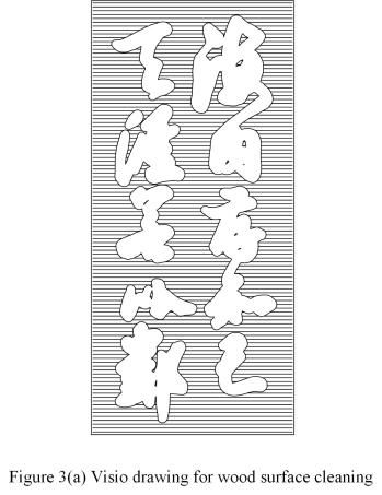
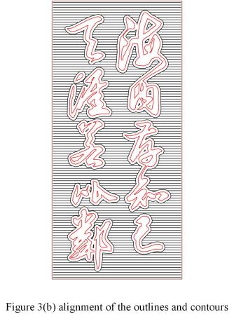
To remove the wood surface outside (and inside in some cases) of the contour, we added parallel line in the area between the contour and the boundary defined by the rectangular box. The distance between two of adjacent parallel lines should be less than the diameter of the CNC bit. For example, if we use a 3mm or 1/8 inch bits for clean the area, the distance may be chosen to be equal to 2.5mm. Such a Visio drawing is shown in Figure 3(a). Figure 3(b) shows the relative positions/alignment of the outlines and the contours.
The Visio drawing is saved in DXF format and used to generate the g-code for the surface cleaning.
Step IV Surface cleaning g-code generation
The Visio drawing described above is used to generate the surface cleaning g-code. The same software: dxf2gcode is used. The procedure is the same as the generation of the g-code for outline cutting. However, since the CNC bit used in this case is stronger, the setting can be more aggressive. For example, in the machine setting section, we can use two passes, each of which is at 0.6mm, for cutting. The feed speed can be 300mm/min to 400mm/min or even fast. Single pass cutting of 1.2mm may also be feasible.
Step V Carving onto wood by CNC machine
The g-code generated in Subsection II is first fed to the CNC machine with the V-shape bit installed. Even though we have very conservative cutting parameters, the operation is usually completed pretty fast. In most cases, it would be less than one hour. Then the g-code generated in the Subsection IV is used to cleaning the wood surface after the CNC bit is changed. Because of the large area involved, the time to perform this operation is usually quite long. It is likely to take a couple to a few hours.
Step VI Manual cleaning
After CNC operations are completed, it is often necessary to perform fine clean-up manually using carving knifes. Such clean-ups are mainly in two areas. First there will some gap between the outline cutting and the contour cutting. Secondly, because the large diameter of the CNC bit for clean up, some area between the outlines of the strikes may not be taken out during surface clean-up. However, in most case, this manual task is not very much involved if the CNC machine does its job correctly. The carved calligraphy using the above procedure is shown below.
Remarks
The SainSmart 3018 CNC did a good job. I would expect similar mini CNCs of different brand should behave similarly. However, I feel any CNC smaller than the 3018 CNC is probably too small for this purpose.
I later bought another CNC machine: the CNC3040. I feel this one is more convenient because larger surface area. Moreover, I also feel its precision is better than CNC3018. However, CNC3040 is about twice as expensive as CNC3018, $450 vs. $200-250, but you get what you paid for.
Among the CNC3018 machines, I feel the CNC3018-Pro is the best based on my testing on its smaller version and other reviews. It is available online such as from Sainsmart, which is also available on Amazon. Amazon also carries similar products of other brands.
I tried different wood materials for calligraphy carving. My favorite is soft maple. It has fine texture and relatively strong. As a result, there is not much a problem for thin broken strikes. In addition, it is somewhat hard but not too hard.
I also tried Poplar and different types of plywood. Poplar is softer, easier to cut, and usable as long as there are no thin and long strikes. Among different plywood, my favorite is Baltic Birch plywood. Similar to the case of poplar, it is usable as long as there are no thin and long strikes.
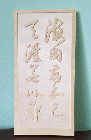
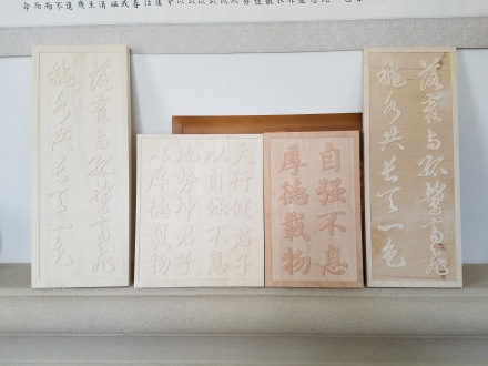
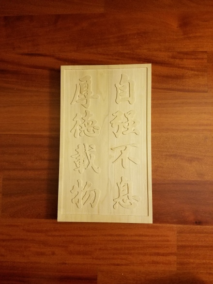
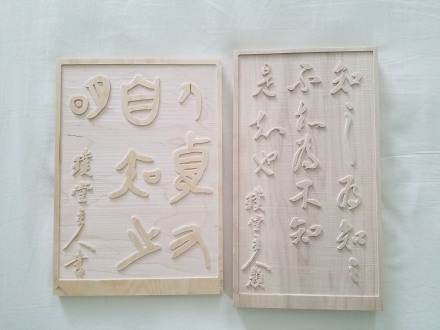
Below are a few photos of what I did previously using the approach described above.

You must be logged in to post a comment.